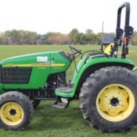
For complete service information also see: 5425, 5625, 5725 Narrow, Orchard & HC Tractors – Operating and Tests Service manual – TM6033 PowrReverser Transmission – John Deere Pune Works (Sr. No. PY1068XXXXXXX, LV12363, LV12364, PY10678, PY10953, LV12781 and Y10952) – CTM900519
In the vast plains of the American heartland, where the soil is rich and the crops are plentiful, one name has become synonymous with agricultural innovation: John Deere. For over a century, this iconic brand has been at the forefront of revolutionizing farming practices, designing machinery that not only increases productivity but also brings a sense of efficiency and convenience to the hardworking farmers.
And among the many groundbreaking models produced by John Deere, the 6120 stands out as a true game-changer that left an indelible mark on the agricultural industry.
When the John Deere 6120 burst onto the scene, it was like a breath of fresh air for farmers who toiled day in and day out on their fields. This state-of-the-art tractor had a range of features that set it apart from its predecessors, making it an instant hit amongst farmers across the country.
From its powerful engine to its advanced technology, the 6120 was a true powerhouse that offered precision, reliability, and incredible performance. But what exactly made the John Deere 6120 so revolutionary? Well, it all starts with its cutting-edge design. Unlike older models, this tractor had a sleek and streamlined appearance, which not only made it visually appealing but also contributed to its exceptional maneuverability.
The compact size of the 6120 allowed farmers to navigate tight spaces with ease, reaching every corner of their fields without any hassle. And with its powerful engine, this tractor was capable of tackling even the toughest terrains, effortlessly plowing through the earth to prepare it for planting. But the true innovation of the John Deere 6120 lies in its advanced technology.
How John Deere 6120 Revolutionized the Agricultural Industry
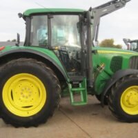
Equipped with sophisticated onboard electronics, this tractor offered farmers an array of digital tools and features that revolutionized the way they approached their work. From GPS-guided navigation systems that ensured precise and efficient cultivation to automated implements that reduced physical strain, the 6120 truly elevated the farming experience to a whole new level.
The impact of the John Deere 6120 on the agricultural industry cannot be overstated. It not only empowered farmers to accomplish more in less time but also contributed to the overall modernization and efficiency of the farming sector. With its remarkable design, powerful performance, and cutting-edge technology, the 6120 has become an enduring symbol of John Deere’s commitment to excellence and their dedication to helping farmers succeed.
So, join us as we delve deeper into the remarkable story of how the John Deere 6120 revolutionized the agricultural industry. From its humble beginnings to its widespread adoption, we’ll explore the key features and innovations that made this iconic tractor such a game-changer.
Get ready to be inspired by the ingenuity and impact of the John Deere 6120, as we uncover the fascinating journey behind its rise to agricultural greatness.
How John Deere 6120 Revolutionized the Agricultural Industry
Caterpillar C7.1 Industrial Engine Troubleshooting Service Manual
C7.1 Industrial Engine 7701-Up (Engine) Manual pdf 384 pages
Troubleshooting Section Electronic Troubleshooting i04029202 Welding Precaution SMCS Code: 1000 Correct welding procedures are necessary in order to avoid damage to the following components:
Electronic Control Module (ECM) on the engine
Clean Emissions Module (CEM)
Sensors
Associated components
Caterpillar C7.1 Industrial Engine Fix Manual
Table of Contents Troubleshooting Section Electronic Troubleshooting Mode Switch Setup 38 Throttle Setup 39 Multiposition Switch Setup 42 Customer Specified Parameters Customer Specified Parameters 43 Customer Specified Parameters Table 50 Customer Specified Parameters Worksheet 53 System Configuration Parameters System Configuration Parameters 57 Symptom Troubleshooting Acceleration Is Poor or Throttle Response Is Poor 59 Alternator Is Noisy 62 Alternator Problem 63 ARD Combustion Supply Air Pressure Is Low 63 ARD Failed to Ignite 65 ARD Is Disabled 69 ARD Loss of Combustion 70 ARD Pilot Fuel Pressure Is High 74 ARD Pilot Fuel Pressure Is Low 77 ARD Temperature Is Low 79 Battery Problem 83 Coolant Contains Oil 83 Coolant Level Is Low 84 Coolant Temperature Is High 85 Cylinder Is Noisy 88 Diesel Particulate Filter Collects Excessive Soot 89 Diesel Particulate Filter Has High Ash Load 92 Diesel Particulate Filter Has High Inlet Pressure 92 Diesel Particulate Filter Has Low Inlet Pressure 94 Diesel Particulate Filter Requires Initial Regeneration 95 Diesel Particulate Filter Temperature Is High 96 Diesel Particulate Filter Temperature Is Low 97 ECM Does Not Communicate with Other Modules 98 ECM Will Not Accept Factory Passwords 99 Electronic Service Tool Does Not Communicate 99 Engine Cranks but Does Not Start 100 Engine Does Not Crank 104 Engine Has Early Wear 105 Engine Has Mechanical Noise (Knock) 106 Engine Misfires, Runs Rough or Is Unstable 106 Engine Overspeeds 109 Engine Shutdown Occurs Intermittently 110 Engine Speed Does Not Change 111 Engine Stalls at Low RPM 112 Engine Top Speed Is Not Obtained 114 Engine Vibration Is Excessive 117 Exhaust Has Excessive Black Smoke 118 Exhaust Has Excessive White Smoke 121 Fuel Consumption Is Excessive 123 Fuel Contains Water 125 Fuel Rail Pressure Problem 126 Fuel Temperature Is High 131 Inlet Air Is Restricted 132 Inlet Air Temperature Is High 133 Intake Manifold Air Pressure Is High 134 Intake Manifold Air Pressure Is Low to 135 Intake Manifold Air Temperature Is High 137 NRS Exhaust Gas Temperature Is High, 138 NRS Mass Flow Rate Problem 140 Oil Consumption Is Excessive 143 Oil Contains Coolant 144 Oil Contains Fuel 145 Oil Pressure Is Low 146 Power Is Intermittently Low or Power Cutout Is Intermittent 148 Valve Lash Is Excessive 151 Troubleshooting with a Diagnostic Code Diagnostic Trouble Codes 152 Diagnostic Code Cross-Reference 159 No Diagnostic Codes Detected 164 Troubleshooting with an Event Code Event Codes 165 Diagnostic Functional Tests 5 Volt Sensor Supply Circuit – Test 167 Analog Throttle Position Sensor Circuit – Test 177 ARD Fuel Supply – Test 182 ARD Ignition – Test 189 ARD Nozzle – Test 204 ARD Nozzle Heater – Test 207 CAN Data Link Circuit – Test 223 Data Link Circuit – Test 227 Diesel Particulate Filter Identification Signal – Test 234 Digital Throttle Position Sensor Circuit – Test 240 ECM Memory – Test 249 Electrical Connectors – Inspect 250 Engine Pressure Sensor Open or Short Circuit – Test 254 Engine Speed/Timing Sensor Circuit 267 Engine Temperature Sensor Open or Short Circuit 274 Engine Temperature Sensor Open or Short Circuit 281 4 KENR9106-01 Table of Contents Ether Starting Aid 290 Fuel Pump Relay Circuit 294 Glow Plug Starting Aid 302 Idle Validation Switch Circuit 309 Ignition Key switch Circuit and Battery Supply Circuit, 314 Indicator Lamp Circuit 321 Injector Data Incorrect 324 Injector Solenoid Circuit 326 Mode Selection Circuit 332 Motorized Valve 336 PTO Switch Circuit, 344 Sensor Calibration Required 347 Solenoid Valve 350 Soot Sensor 359 Throttle Switch Circuit 363 Valve Position Sensor 366 Water In Fuel Sensor 377 Index Section Index 381
Doosan Moxy MT36 Articulated Dump Truck Service Parts Manual
Removal of engine assembly Lifting the engine Engine identification Fuel system Schematic diagram of the fuel system Overflow valve General FUEL Fuel filter Water separating prefilter Feed pump Diagnostic procedure Use of diagnostic kit, machine 810001 – 810052 Use of diagnostic kit, machine 810053 – Measurement Ecom standard settings code Engine control unit, ECU Wiring and cable duct Throttle position sensor Positions of sensors for ECU Diagnostic lamp and switch (810001 – 810035) Diagnostic lamp and switch (810036 – ) Fault codes How to read fault codes from the ECU control unit Flash codes tables Overview of flash codes for coordinator Renewing the control unit Removing the ECU wiring Cylinder head Special tools Cylinder head, parts view. Valve mechanism Dismantling Renewing the valve stem seal Replacement of valve seats Machining the valve seats insert Renewing the valve guides Renewing PDE unit injector sleeves Assembly
Doosan Moxy MT36 Articulated Dump Truck Service Parts Manual
Fitting PDE Injectors Fitting the PDE injector Adjusting unit injectors Adjusting the valve clearance and unit injectors Checking, adjusting the PDE injector rocker arms Turbocharger General Special tools Measuring radial clearance and axial clearance Renewing the turbocharger Pistons and cylinder liners Special tools Connecting rods Removing and dismantling connecting rods and pistons Renewal of bearing bushing in connecting rod Pistons Assembling piston and connecting rod Cylinder block Cylinder liner Removing the cylinder liners Measuring the cylinder liner height Fitting the cylinder liners Fitting the piston and connecting rod Flywheel and flywheel housing Special tools Removing the flywheel Renewing the rear crankshaft seal Removing the flywheel housing Fitting flywheel housing Fitting the flywheel Timing gears Gear drive Belt drive coolant pump, generator, and AC compressor Renewing the seal in the front cover Crankshaft damper Timing gear, view exploded Special tools Intermediate gear Camshaft gear Crankshaft gear Camshaft Replacement of camshaft bearing Crankshaft Removal Fitting Lubrication system Oil pump Lubrication oil ways Oil pressure Oil cooler, engine Oil cooler view Renewing seals Oil filter Centrifugal oil cleaner Dismantling and assembly Cooling fan Cooling system View of the cooling system Circulation View of the radiator system Disassemble the cooling unit Thermostat and thermostat housing Thermostat Coolant pump External cleaning Internal cleaning Specifications General information Electrical system Cylinder head Turbocharger Pistons and cylinder liners Connecting rods Flywheel and flywheel housing Timing gear Lubrication system Troubleshooting tables White smoke White smoke, water vapour Black smoke when running/under load Black smoke on starting Blue smoke Fuel in the oil Oil in coolant Coolant/water in oil Low oil pressure High oil pressure (Engine warmed up) Abnormal wear (liner, piston rings, etc.) Vibration, no driven components engaged Delivery pipe fractures External corrosion on cylinder liner Engine difficult to start Fluid stroke Knocking noise High oil consumption High fuel consumption Low compression Low engine output Hot engine Cold engine Coolant loss Polluted coolant Engine heater High oil temperature High exhaust temperature Low charge air pressure Low fuel pressure Low system voltage High system voltage External oil leakage External fuel leakage External coolant leakage
Doosan Moxy MT36 Articulated Dump Truck Service Parts Manual
Applies to: DD110B, DD120B, DD140B IR, P7170 IR, PF6160 IR, PF6170 IR, P7110 IR AND P6110 IR
PRESS INFORMATION New Volvo pavers tracked P7110 or wheeled P7170 provide operators with maximum versatility to suit the needs of any job; delivering the power, precision and quality that highway paving contractors demand. Volvo pavers are known for their high-quality output, and the new P7000 series pavers — born from the Blaw-Knox legacy — are no exception. Powered by a Volvo 235 hp (175 kW) Tier 4i-compliant D8 engine, the P7110 and P7170 are more efficient than previous models, with decreased engine emissions and increased fuel efficiency. The engine’s diesel particulate filter (DPF) and active, semi-automatic regeneration process work without interruption, maximizing machine performance and productivity. Starting the paver in cold weather is made easier thanks to an available pump decoupler that disengages non-essential pumps for more consistent start-ups.
7000 Paver Series
volvo p7110 P7170 IR tracked paver Repair Manual
The P7110 and P7170 are powerfully precise, with a four-sensor feed system that automatically regulates the delivery and flow of material to match paver speed, ensuring smooth, even paving. With the simple press of a button, the driver and screed operator can extend hydraulically-powered, two-stage tunnels, which offer concise control of material flow across the paving width, resulting in a high quality mat. Flow gates, as well as other options, are available to tailor machines to meet individual contractor’s needs. Blaw-Kote® protective coating prevents asphalt from sticking to vital components, providing better machine wear and longer life. The P7110 and P7170 pavers offer near 360-degree visibility, giving operators a safe, all-around view of the paving process for greater comfort and confidence. The signature low, single-level platform permits the operator to move freely, easily and safely. Large steps, handrails and anti-slip plates allow the operator to access and exit the platform safely. Dual-rotating, tiltable consoles deliver greater versatility, allowing operators to choose from which side of the machine they prefer to operate. Operator productivity is improved with adjustable seats that can be extended beyond the edge of the paver, offering improved visibility and comfort. Steering on the tracked P7110 is controlled by two levers on each seat console, while the steering wheel maneuvers the wheeled P7170. Controls are intuitively clustered by function for ease of use and are backlit for night use or low-light conditions.
Maintenance on these models is made easy with ground level accessibility to service points and wide opening service doors on the deck surface. Machine lifetime and productivity are further enhanced through a variety of customer service support channels. Customer Service Agreements are available, which provide customers with maximum cost control and minimum downtime. Access is also made available to the Volvo Road Institute, a program which, for nearly 50 years, has provided customers with relevant educational content delivered by industry experts, helping customers maximize productivity and machine performance.
As with all Volvo products, the P7110 and P7170 pavers are backed by an extensive service network that provides the peace of mind that comes with an experienced worldwide network of technicians, workshops and dealers.
volvo p7110, P7170 IR tracked paver Repair Manual
Price: $63.90
volvo p7110 P7170 IR tracked paver Repair Manual
235-hp Tier 4 Interim D8 engine Four-sensor feed system automatically regulates delivery and flow of material to match paver speed 12-ton capacity hopper with synchronized folding, hydraulic front hopper wings Hydraulically powered two-stage tunnels for concise control of material flow across paving width Proportional auger speed control and hydraulic auger height adjustments Conveyors have reverse feature to control material Low, single-level platform Dual-rotating, tiltable consoles for operation from either side of machine Blaw-Kote protective coating prevents asphalt from sticking to components Available pump decoupler disengages non-essential pumps for consistent start-ups P7110 has continuous rubber track with tandem bogie system P7170 has two drive wheels, four front bogies and an optional front-wheel assist Max paving width: 26 ft. Max paving depth: 12 in.
Manual Description This technical manual is written for an experienced technician and contains sections that are specifically for this product. It is a part of a total product support program.
The manual is organized so that all the information on a particular system is kept together. The order of grouping is as follows:
John Deere X485, X575 and X585 Garden Tractors TECHNICAL MANUAL
Table of Contents
Specifications and Information
Identification Numbers
Tools and Materials
Component Location
Schematics and Harnesses
Theory of Operation
Operation and Diagnostics
Diagnostics
Tests and Adjustments
Repair
Other NOTE: Depending on the particular section or system being covered, not all of the above groups may be used. The bleed tabs for the pages of each section will align with the sections listed on this page. Page numbering is consecutive from the beginning of the Safety section through the last section. We appreciate your input on this manual. If you find any errors or want to comment on the layout of the manual please contact us.
Safety Specifications and Information Engine – Gas (Air-Cooled) Engine – Gas (Liquid-Cooled) Electrical Hydraulics Power Train – Hydrostatic Steering Brakes Attachments Miscellaneous
All information, illustrations, and specifications in this manual are based on the latest information at the time of publication. The right is reserved to make changes at any time without notice.
Language: English Format: PDF Service Manual: 576 Pages, copy 03 and 2004
John Deere is a name synonymous with agricultural innovation and high-quality farming equipment. If you’re a proud owner or operator of a John Deere 5200, 5300, 5400, or 5500 tractors, you already know the value of having reliable and efficient machinery in your farm arsenal. To maximize the performance of your tractor and ensure its longevity, you need access to the Operator’s Manual, a crucial resource that provides guidance on operation, maintenance, and troubleshooting.
In this article, we’ll explore the significance of the John Deere Operator’s Manual for these specific tractor models and how it can empower you to optimize your farming operations. Table of Content of the John Deere 5200, 5300, 5400, 5500 Tractors
John Deere 5200, 5300, 5400, and 5500 Tractors Operators Manual
Foreword John Deere Dealers General Information Safety
General Specifications
Fuel and Lubricants Serial Number Locations Features and Accessories Engine Repair Engine Cooling System Fuel and Air Repair Fuel System Air Intake System Speed Control Linkage Electrical Repair Battery, Starter, and Alternator Electrical System Components Wiring Harness
Collar Shift/TSS Transmission Hydraulic Reverser Transmission Rear PTO Drive Shaft-Collar Shift/TSS Transmission Rear PTO Drive Shaft-Hydraulic Reverser Transmission Differential Final Drives Mechanical Front-Wheel Drive Creeper Assembly Steering and Brake Repair Steering Repair Brake Repair Hydraulic Repair Hydraulic Pump and Filter Hydraulic Oil Cooler Rock shaft Dual Selective Control Valve Single (Third) Selective Control Valve Hydraulic Mid-Mount Coupler Hydraulic Power Beyond Miscellaneous Repair Front Axle-2WD Wheels
3-Point Hitch
Operator Station Repair Seat and Support ROLL-GARD™ Cab Components Air Conditioning System Heating System Operational Checkout Procedures Operational Checkout Procedures Engine Operation, Tests, and Adjustments Component Location Theory of Operation Diagnosis, Tests, and Adjustments Fuel/Air Operation, Tests and Adjustments Component Location Theory of Operation Diagnosis, Tests and Adjustments Electrical System Operation, Tests and Adjustments Component Location Theory of Operation Diagnosis, Tests and Adjustments Wiring Schematics Power Train Operation, Tests and Adjustments Component Location-Collar Shift/TSS Transmission Component Location-Hydraulic Reverser Transmission Theory of Operation-Collar Shift/TSS Transmission Theory of Operation-Hydraulic Reverser Transmission Diagnosis, Tests and Adjustments-Collar Shift/TSS Transmission Diagnosis, Tests and Adjustments-Hydraulic Reverser Steering and Brake Operation, Tests and Adjustments Component Location Theory of Operation Diagnosis, Tests and Adjustments Hydraulic System Operation, Tests and Adjustments Component Location Theory of Operation Diagnosis Hydraulic Tests-Without SCV Hydraulic Tests-With SCV Hydraulic Tests-All Adjustments Hydraulic Schematics Operator Station Component Location Theory of Operation Diagnosis, Tests and Adjustments Dealer Fabricated Tools Dealer Fabricated Tools
John Deere 5200, 5300, 5400, and 5500 Tractors Operators Manual
READ THIS MANUAL carefully to learn how to operate and service your Tractor correctly.
The John Deere 5200, 5300, 5400, 5500 Tractors Technical manuals are divided in two parts: Technical manuals are divided in two parts: repair and diagnostics. Repair sections tell how to repair the components. Diagnostic sections help you identify the majority of routine failures quickly.
Technical Manuals are concise guides for specific-machines. Technical manuals are on-the-job guides-containing only the vital information needed for-diagnosis, analysis, testing, and repair.
To ensure John Deere continue to deliver peak performance, having access to the John Deere 4510, 4610, 4710 Tractor Service Manual is essential. In this article, we’ll explore the significance of this manual and the benefits it provides for tractor owners and operators.
The Importance of the Service Manual:
Maintenance Guidance: The service manual for the John Deere 4510, 4610, and 4710 tractors serves as a comprehensive guide for routine maintenance and servicing. It outlines regular check-ups and the proper steps to take to keep the tractors running efficiently.
Machine model : TM1986
John Deere 4510, 4610, and 4710 Compact Utility Tractors Service Manual
Manual Covers: *Safety *Specifications and Information *Engine *Electrical *Power Train(Gear) *Power Train(eHydro) *Power Train(ePowrReverser) *Power Train(Final Drive) *Hydraulics *Steering *Brakes *Miscellaneous AND MORE…
John Deere 4510, 4610, and 4710 Tractor Service Manual
Price: $39.00
John Deere 4510, 4610, and 4710 Tractor Service Manual, all pages are printable, so run off what you need & take it with you into the garage or workshop. Save money $$ by doing your own repairs! It make it easy for any skill level with these very easy to follow, step-by-step instructions! Instant download means no shipping cost or waiting for a CD to arrive in the mail…you will receive this manual today via instant download on completion of payment via our secure payment processor. We accept all major credit/debit cards/paypal. Instant download! Thank you for visiting!